January 04, 2012
Here are details of the screen design.
Materials:
* 3 particle board sheets 4 x 8 feet
* 1 x 3, 2 x 3, 2 x 8 and 2 x 10 inches pine lumber,
* deck screws 8 x 3 and 8 x 2 ½.
* Plastic window moldings,
* machine screws
* Velcro (industrial strength)
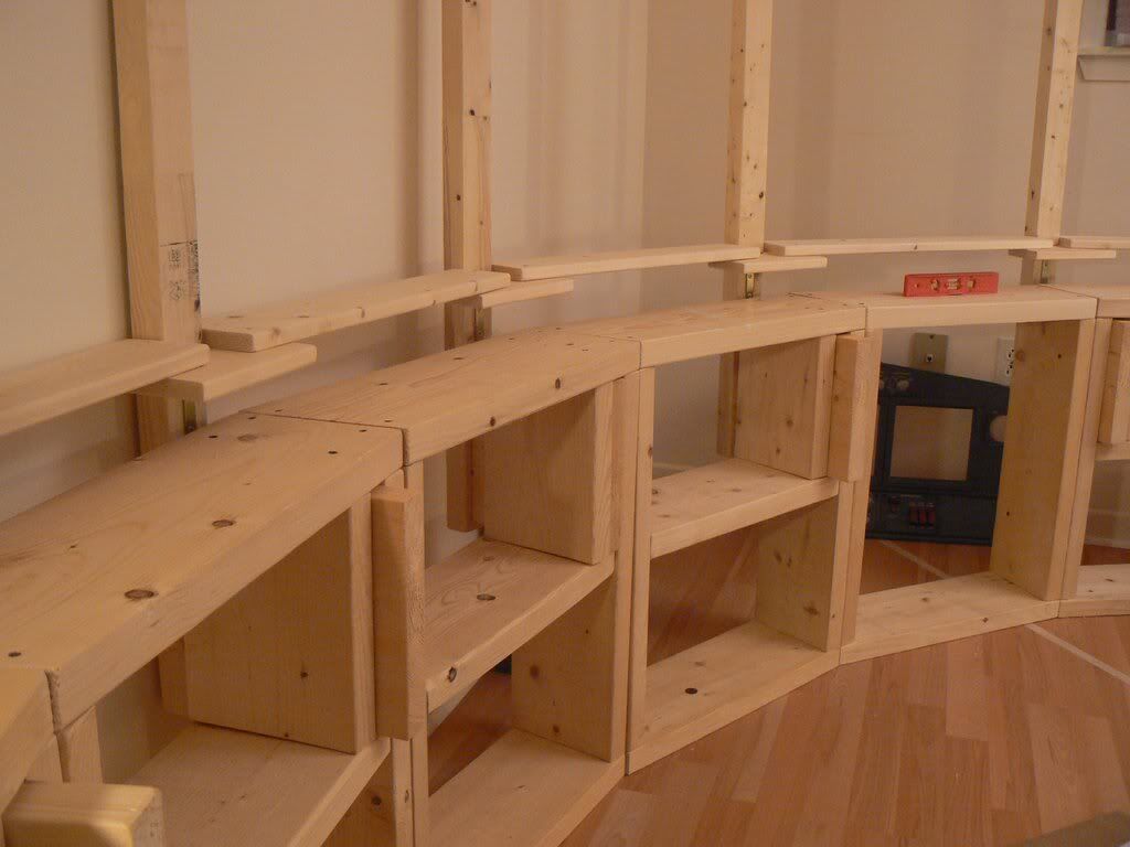
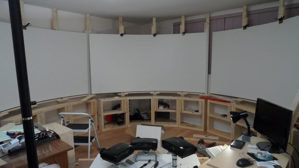
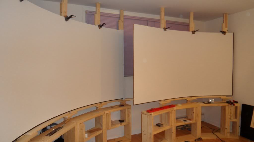
The screen base is made from standard 2 x 8 pine lumber. There are 12 sections like this,
each one has a shelf (except two sections that I use to crawl behind the screen) and held together by standard 8 x 3 deck screws.
The sections connected together also by a few deck screws 8 x 2 ½.
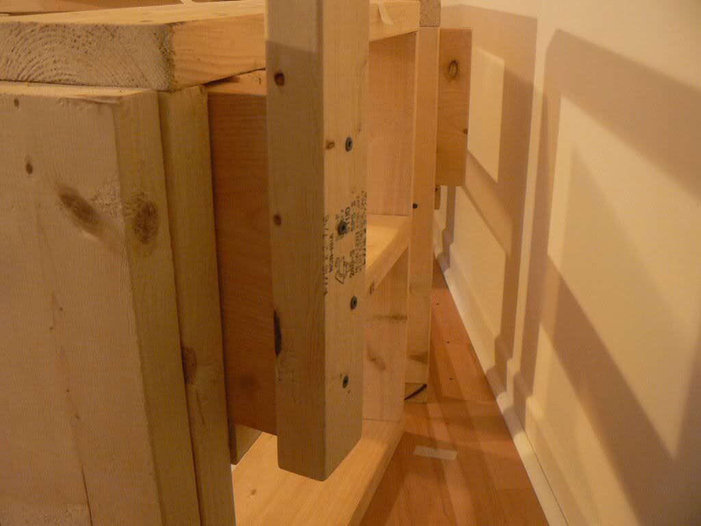
There are 12 screen posts (2" x 3") the posts ~ 170 cm in height installed the following way:
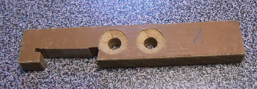
There is a piece of 2 x 10 lumber which is screwed to the bottom end of the post

This piece tightly slides in a vertical slot formed by the section side and another vertical piece. This allows changing the actual screen radius at any post.
After adjustment, the piece is just screwed in with a couple of deck screw 8 x 2 ½ through the side. It can be screwed out and readjusted if necessary in a matter of minute. The height of the slot is a bit bigger than a sliding piece, so the posts can be adjusted to make a desired vertical.
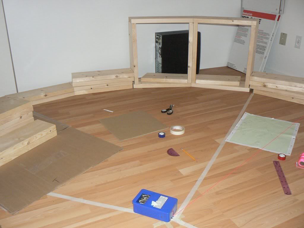
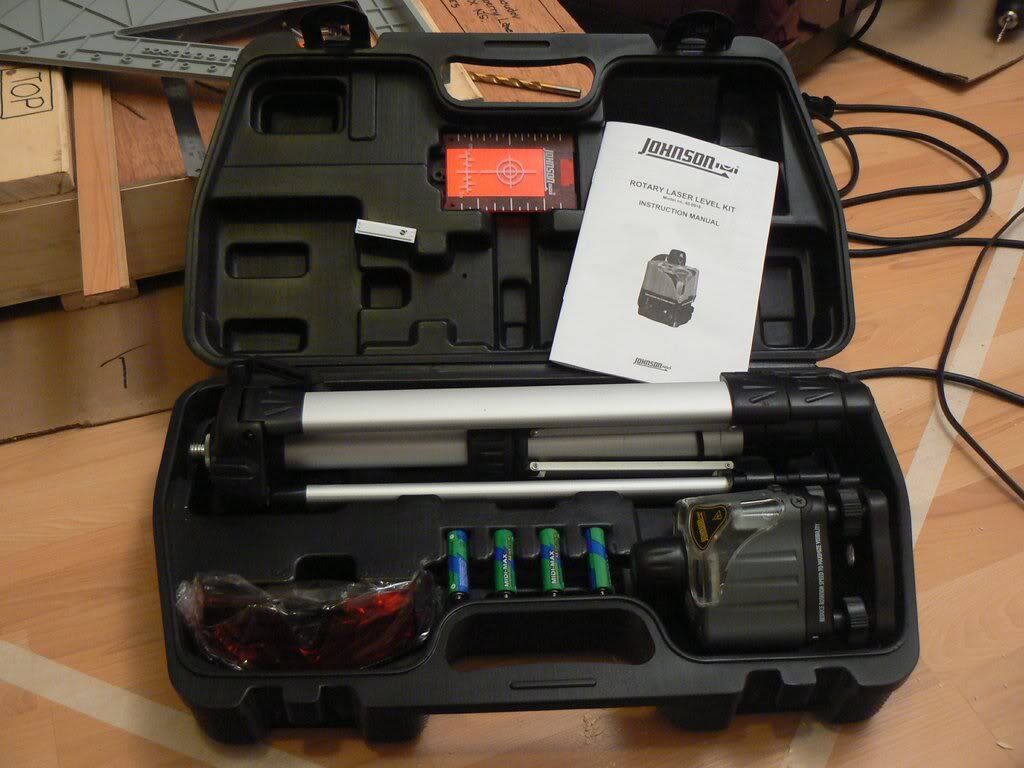
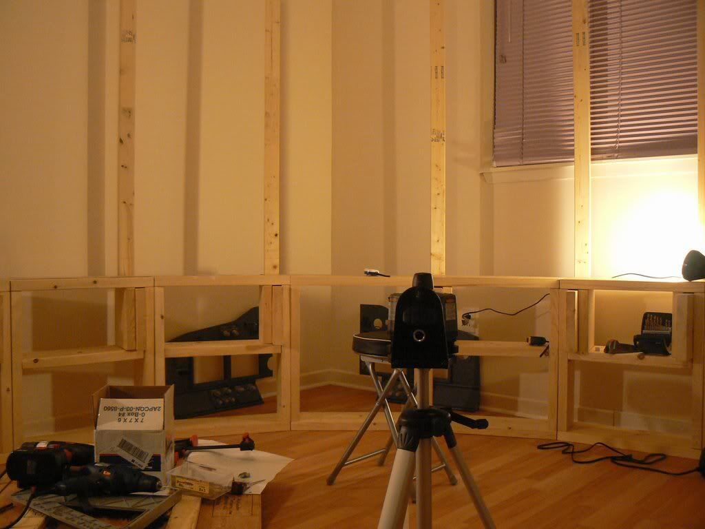
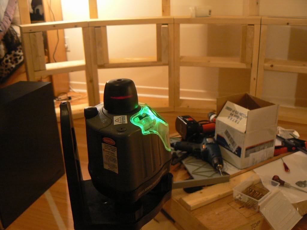
There is no real precision required to build the screen, except adjusting the screen height that was done with the rotating laser level.
So: the base sections are built, the post bases inserted into the slots, then adjusted vertically and horizontally (roughly achieving the desired screen shape and radius). Sections screwed in together.
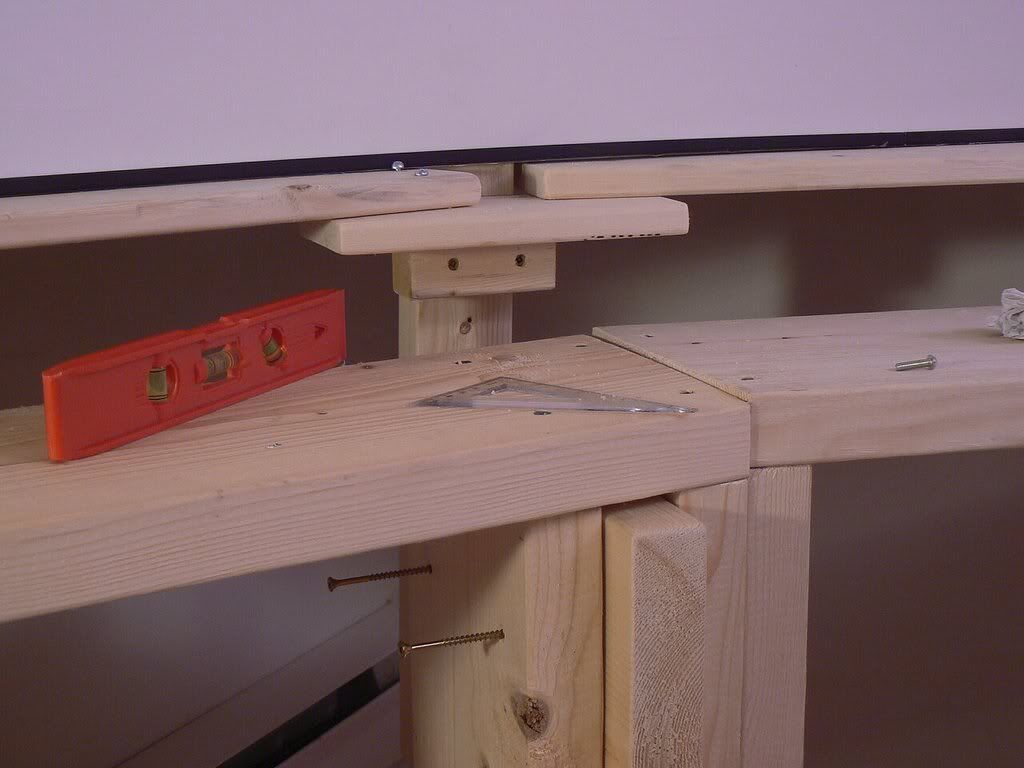
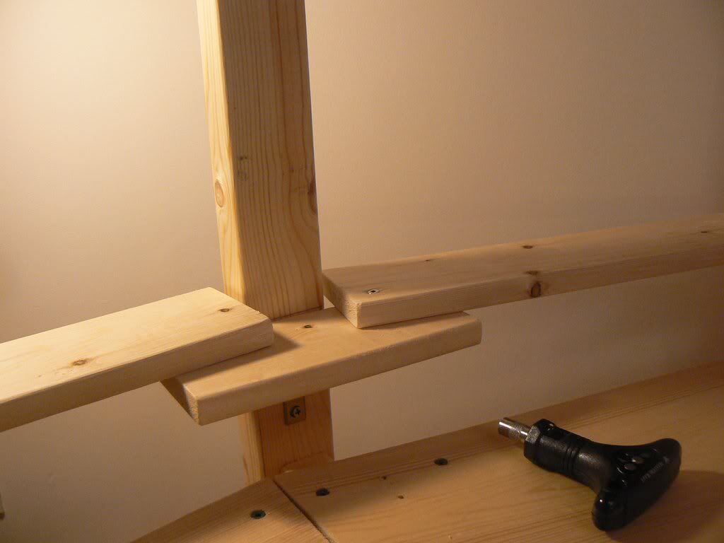
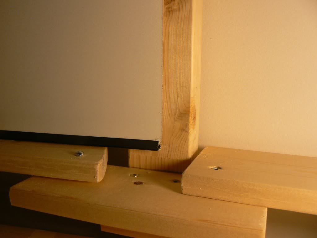
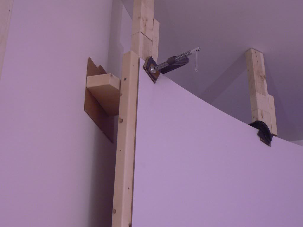
Then actual screen supports are built on each post. They look like this:

Since the radius of screen can change at any post, it is not possible to put just one rigid shelf to stand the screen on, or screw the screen to the posts. The screen support shelves are built in pieces that lay on the small support blocks screwed to each post.
The position of support blocks is aligned up with the rotating laser level.
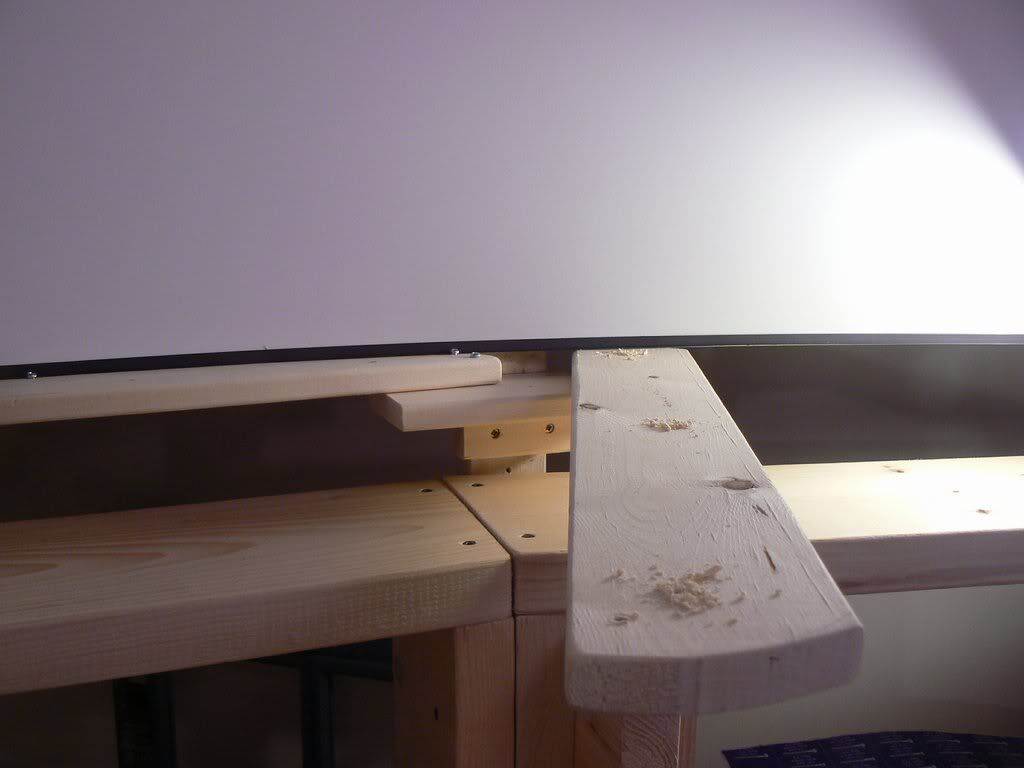
The screen shelves pieces made of 1 x 3 boards just screwed in by one screw on the left side, the right side can slide on the next supporting block when you adjust them.
When the shelves are adjusted, the hole is drilled through the support shelf and underlying block and the machine screw is inserted like a pin into it. Just inserted, not screwed in. It is enough to prevent the shelf piece from moving.
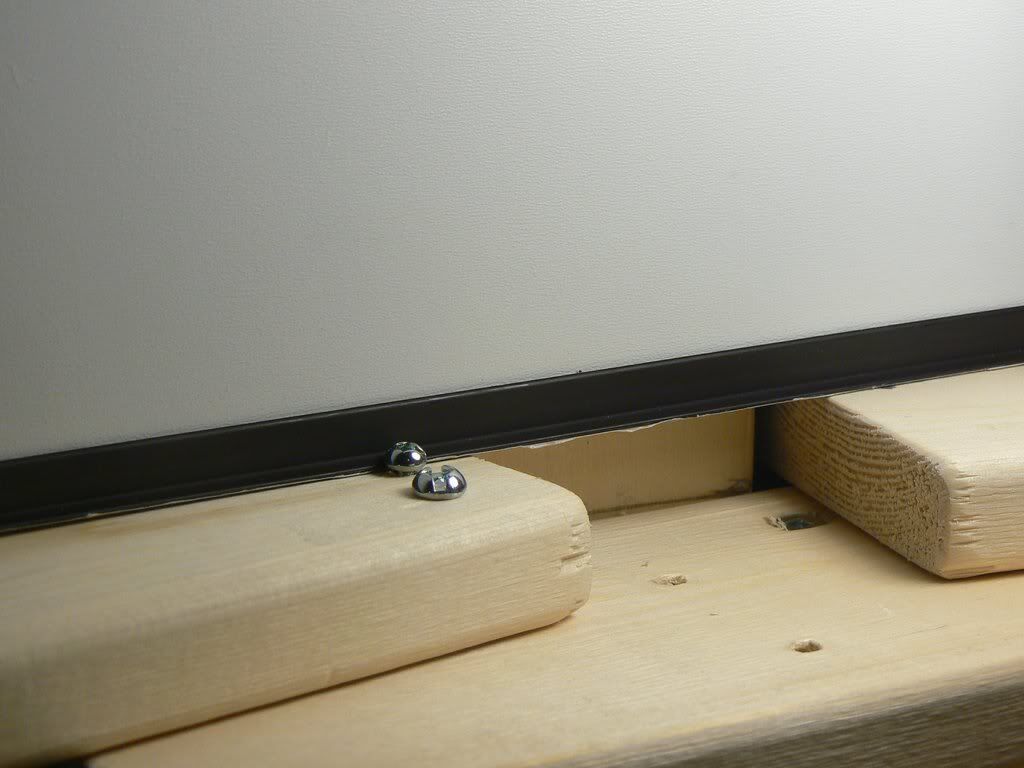
The screen sheet just stands on the shelves and held from moving by other machine screws inserted into the shelf at the desired positions making the arc.
Here is the trick how to shape and hold the screen without the screws in it.
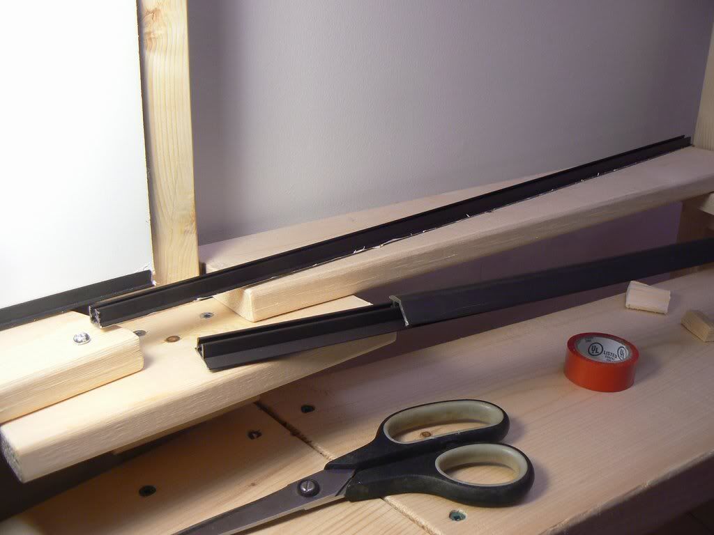
I bought a few plastic window moldings that look like this:
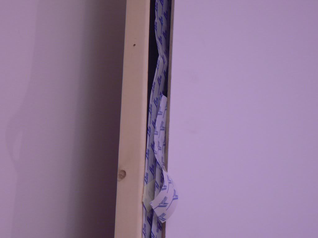
The top part you don’t need, so take the part with the slot and cut off its bigger shelf with the scissors. The slot size is ~ 5mm and it fits tightly over the bottom edge of the screen. Also those moldings have the sticky layer on bottom that I had to scrape off. The height of the molding is also ~ 5 mm, so it does not take away any significant screen height.
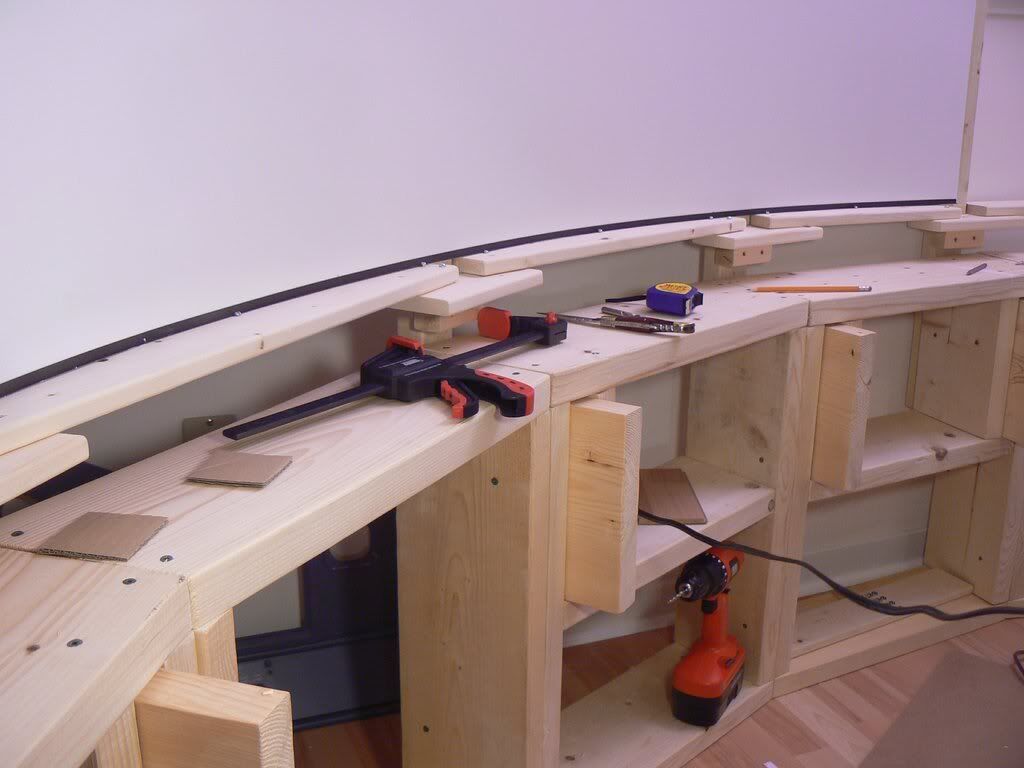
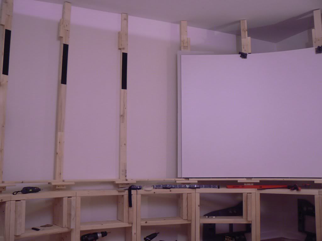
Now, when the screen sheet has the molding on its bottom I just lift it up, bend and place on the support shelves. Then I use the clamps to hold its upper part to the posts. It all can be easily done by one person.
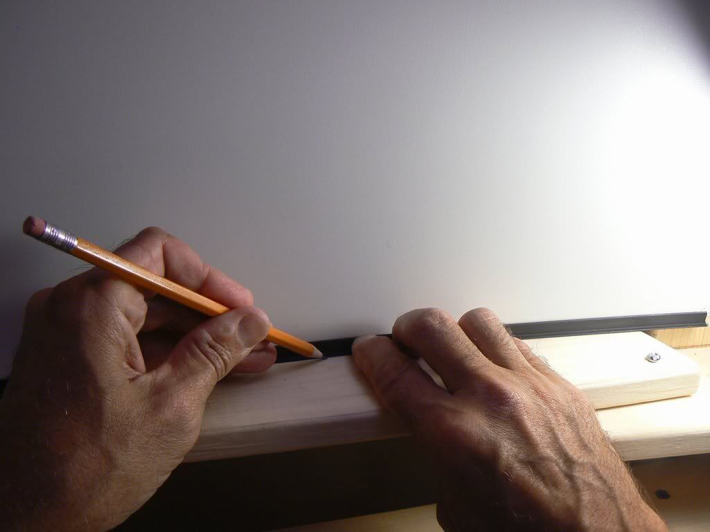
After this I evaluate the shape on bottom, adjust it and mark the positions for the machine screws that will hold the shape where necessary.
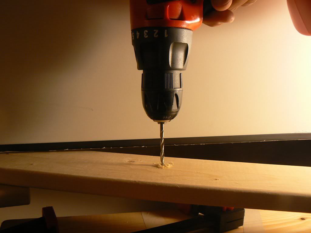
When the positions for the screw holes are marked, I rotate the particular shelf out of the screen and drill the hole.
Then I insert the machine screws and rotate the shelf back in position and re-insert the screw that holds its right side.
So, the machine screws are stopping the screen from moving in radial direction and pushing the molding with the screen edge to desired position, and not damaging the actual screen surface. If I want to readjust the part of screen – I just mark and drill the new holes.
The clamps on top of the screen sheet are used just temporarily, until I make the entire screen and image adjustments. To hold the screen in use I initially decided to use the industrial strength Velcro (from Home Depot) which is located on the posts and the back of the screen. While the adjustments are not finished, there is a piece of cardboard inserted between the Velcro surfaces so they do not stick yet. (Note: later development proved Velcro unnecessary. Screen sheets are left floating.)
The screen holds its shape very well.
Instead of Velcro, I can apply the same molding+stopping screws system on the top of the screen.
Also, to make the structure more rigid one can additionally fix the top of the posts to the ceiling (of course only after all image adjustments are done).
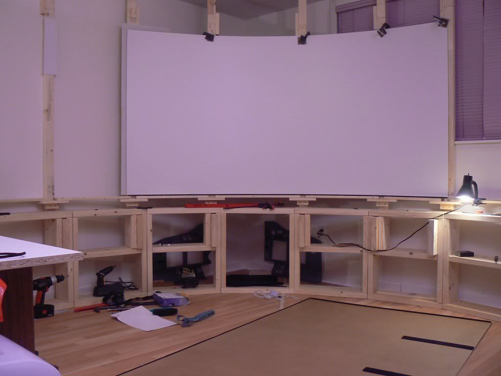
Right now the whole screen structure just stands on the floor.
I already did one adjustment by rotating the whole screen ~10 degrees counterclockwise. Just separated it in 3 blocks, moved each one to new position screwed in again. All took about 10 minutes.
I believe this screen design is especially convenient for those who live in apartments. It can be disassembled/reassembled within an hour.
The expansion and contraction problem does not really exist in this design. The screen sheets are floating on supporting shelves and can push each other out. The screen is standing for 2 month now and I did not notice any seams problem. If the gap increases I could just push one of the outer sheets in to close the gap. That’s why I now inclined to apply the molding system on top of the screen too instead of using Velcro. Maybe Velcro will stay for the central sheet and side sheets will be held by moldings.
Building of this screen structure is easy and does not require any significant precision. The only precise thing needed is to level the screen bottom horizontally which is very convenient using the rotating laser level.
The posts have extension pieces on top. Just because it is much easier to operate a somewhat shorter post that does not try to scrape the ceiling. Later the black material will be attached to them between screen and the ceiling. I bought a bunch of nice black rugs in Wal-Mart for 99c apiece.
The total cost of the screen is about $150.
****
January 16, 2012
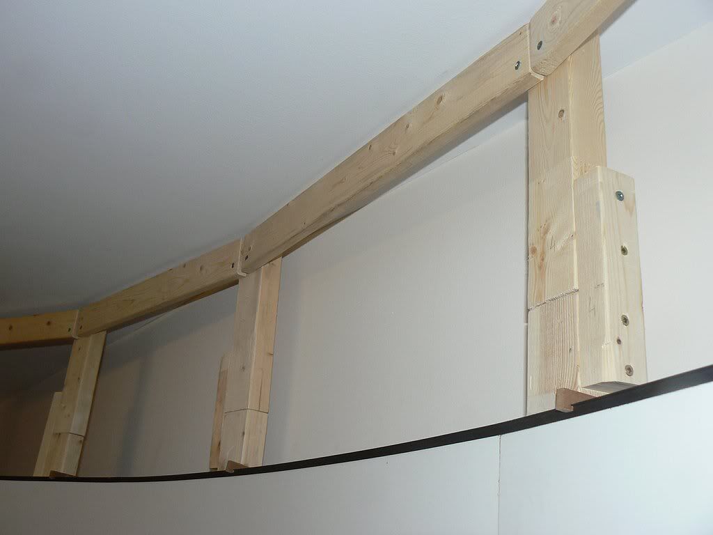
The screen design is finalized. I abandoned the idea of holding the back of screen with Velcro – there is no need in that. The molding system in the bottom is enough for the whole screen to hold its shape. I removed the temporary clamps, installed the plastic moldings along the screen top edge and made 12 holders like this:
The holders are screwed to the posts like this:
After that I connected the tops of the boards with planks like this:
The planks are for fixing the black material, they also give the structure some extra rigidity.
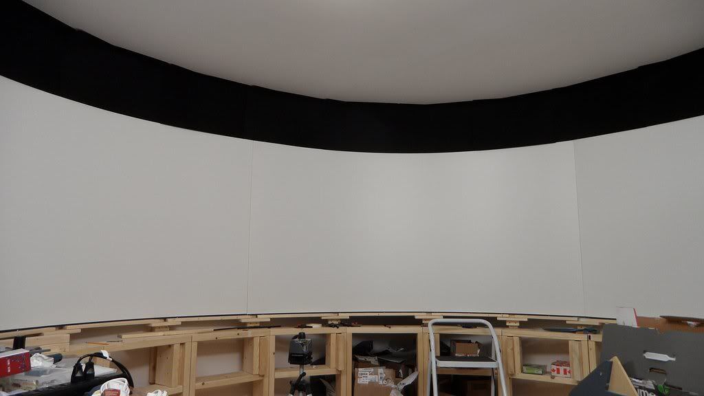
The black stuff around screen is made out of 16” x 24” floor mats that I’ve bought in Wal-Mart for 99c each.
They are attached with just two small Velcro pieces each. Same mats also installed on Velcro to hide the screen base.
Here are details of the screen design.
Materials:
* 3 particle board sheets 4 x 8 feet
* 1 x 3, 2 x 3, 2 x 8 and 2 x 10 inches pine lumber,
* deck screws 8 x 3 and 8 x 2 ½.
* Plastic window moldings,
* machine screws
* Velcro (industrial strength)
The screen base is made from standard 2 x 8 pine lumber. There are 12 sections like this,

each one has a shelf (except two sections that I use to crawl behind the screen) and held together by standard 8 x 3 deck screws.

The sections connected together also by a few deck screws 8 x 2 ½.
There are 12 screen posts (2" x 3") the posts ~ 170 cm in height installed the following way:
There is a piece of 2 x 10 lumber which is screwed to the bottom end of the post

This piece tightly slides in a vertical slot formed by the section side and another vertical piece. This allows changing the actual screen radius at any post.

There is no real precision required to build the screen, except adjusting the screen height that was done with the rotating laser level.

So: the base sections are built, the post bases inserted into the slots, then adjusted vertically and horizontally (roughly achieving the desired screen shape and radius). Sections screwed in together.
Then actual screen supports are built on each post. They look like this:

Since the radius of screen can change at any post, it is not possible to put just one rigid shelf to stand the screen on, or screw the screen to the posts. The screen support shelves are built in pieces that lay on the small support blocks screwed to each post.

The position of support blocks is aligned up with the rotating laser level.


The screen shelves pieces made of 1 x 3 boards just screwed in by one screw on the left side, the right side can slide on the next supporting block when you adjust them.

When the shelves are adjusted, the hole is drilled through the support shelf and underlying block and the machine screw is inserted like a pin into it. Just inserted, not screwed in. It is enough to prevent the shelf piece from moving.

The screen sheet just stands on the shelves and held from moving by other machine screws inserted into the shelf at the desired positions making the arc.

Here is the trick how to shape and hold the screen without the screws in it.
I bought a few plastic window moldings that look like this:

The top part you don’t need, so take the part with the slot and cut off its bigger shelf with the scissors. The slot size is ~ 5mm and it fits tightly over the bottom edge of the screen. Also those moldings have the sticky layer on bottom that I had to scrape off. The height of the molding is also ~ 5 mm, so it does not take away any significant screen height.
Now, when the screen sheet has the molding on its bottom I just lift it up, bend and place on the support shelves. Then I use the clamps to hold its upper part to the posts. It all can be easily done by one person.

After this I evaluate the shape on bottom, adjust it and mark the positions for the machine screws that will hold the shape where necessary.

When the positions for the screw holes are marked, I rotate the particular shelf out of the screen and drill the hole.


Then I insert the machine screws and rotate the shelf back in position and re-insert the screw that holds its right side.

So, the machine screws are stopping the screen from moving in radial direction and pushing the molding with the screen edge to desired position, and not damaging the actual screen surface. If I want to readjust the part of screen – I just mark and drill the new holes.
The clamps on top of the screen sheet are used just temporarily, until I make the entire screen and image adjustments. To hold the screen in use I initially decided to use the industrial strength Velcro (from Home Depot) which is located on the posts and the back of the screen. While the adjustments are not finished, there is a piece of cardboard inserted between the Velcro surfaces so they do not stick yet. (Note: later development proved Velcro unnecessary. Screen sheets are left floating.)


The screen holds its shape very well.
Instead of Velcro, I can apply the same molding+stopping screws system on the top of the screen.
Also, to make the structure more rigid one can additionally fix the top of the posts to the ceiling (of course only after all image adjustments are done).
Right now the whole screen structure just stands on the floor.
I already did one adjustment by rotating the whole screen ~10 degrees counterclockwise. Just separated it in 3 blocks, moved each one to new position screwed in again. All took about 10 minutes.


I believe this screen design is especially convenient for those who live in apartments. It can be disassembled/reassembled within an hour.
The expansion and contraction problem does not really exist in this design. The screen sheets are floating on supporting shelves and can push each other out. The screen is standing for 2 month now and I did not notice any seams problem. If the gap increases I could just push one of the outer sheets in to close the gap. That’s why I now inclined to apply the molding system on top of the screen too instead of using Velcro. Maybe Velcro will stay for the central sheet and side sheets will be held by moldings.
Building of this screen structure is easy and does not require any significant precision. The only precise thing needed is to level the screen bottom horizontally which is very convenient using the rotating laser level.
The posts have extension pieces on top. Just because it is much easier to operate a somewhat shorter post that does not try to scrape the ceiling. Later the black material will be attached to them between screen and the ceiling. I bought a bunch of nice black rugs in Wal-Mart for 99c apiece.
The total cost of the screen is about $150.
****
January 16, 2012
The screen design is finalized. I abandoned the idea of holding the back of screen with Velcro – there is no need in that. The molding system in the bottom is enough for the whole screen to hold its shape. I removed the temporary clamps, installed the plastic moldings along the screen top edge and made 12 holders like this:

The holders are screwed to the posts like this:

After that I connected the tops of the boards with planks like this:

The planks are for fixing the black material, they also give the structure some extra rigidity.
The black stuff around screen is made out of 16” x 24” floor mats that I’ve bought in Wal-Mart for 99c each.
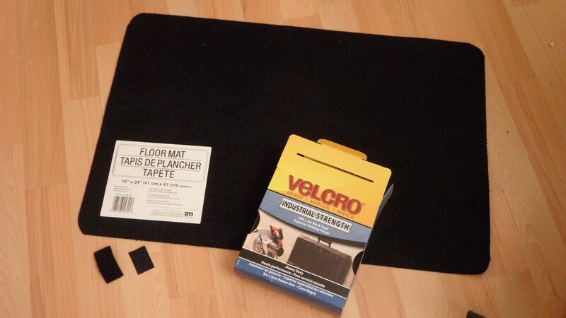
They are attached with just two small Velcro pieces each. Same mats also installed on Velcro to hide the screen base.

Outstanding craftsmanship which provides many idea for my own set-up. Thank you for documenting the procedure, WilloW
ReplyDelete